Blog

Lean Visual Systems Part 1: The Wallpaper Problem

Lean Visual Systems Part 1: The Wallpaper Problem

This is the first post in a three-part series on lean visual systems — how they lose effectiveness over time, how to keep them sharp, and how we approach visual management on our own shop floor.

Visual management is one of the core principles of lean manufacturing for good reason. Strong visual systems compress decision-making. They make the enemies of lean — waste, variation, and overburden — easy to see.

But visual systems vary in their effectiveness, and they can weaken over time. Information piles up. Processes change. Time passes. Slowly, a visual control risks fading into the background. Wallpaper.

Once a system becomes wallpaper, operators tend to fall back on memory instead of reading it. That sets the stage for one of the most frustrating failures in manufacturing: the process wasn’t followed, even though the instructions were right there.

At Micron, it is our firm belief that weaknesses in systems should be diagnosed before any blame is distributed to the people working those systems. While a natural response to missed work instructions is to remind the operator to pay better attention, “wallpaper” problems are actually a sign that the visual systems in place must be improved.

Visual Systems that Resist Wallpaper

People stop noticing what they get used to. So the best defense against wallpaper is a lean visual system that stays active, owned, and right-sized.

Start by keeping it current. Processes and information needs shift constantly on a production floor, but visual aids often lag behind. An outdated board might seem to serve “well enough” to leave alone. In reality, an inaccurate display quietly trains people to trust memory over what’s in front of them.

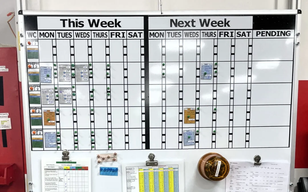
A system also needs to earn attention, and interaction helps. Moving a thumbtack for a PM. Checking a box with a dry-erase marker. Sliding a job card from “not started” to “in process” to “done.” Small physical actions like these build the habit of processing the information, not just glancing.

Ownership matters just as much as design. Every visual control benefits from someone ultimately responsible for keeping it accurate and useful. Wherever possible, also enlist the help of not only the official owner, but everyone who relies on it day to day. The people using a system are often the first to notice when it’s drifted from reality, and their feedback is what keeps it honest.

Finally, there’s a Goldilocks level of detail worth aiming for. Too little information forces people to guess — a real source of variation and error. Too much, and the important parts get lost in the noise. The display itself works best carrying only the most critical information, with supporting detail living in a reference document close at hand rather than competing for space on the board.

Seeing like a First Timer

Even a well-designed visual management system will drift eventually. No board stays accurate forever, and the habits we accumulate with experience provide mental shortcuts that save us from paying attention. The familiarity we develop with our systems over time is what eventually makes us stop seeing them.

Getting an accurate read on a visual system means finding a way to see it again as if for the first time — the way someone brand new to the floor would.

Part 2 covers exactly that: how to audit a lean visual system for signs it’s become wallpaper, and a framework we’ve found useful for refreshing our own.

Is Leadership Continuity Part of Your CNC Supplier Review?

Is Leadership Continuity Part of Your CNC Supplier Review?

In the supplier review process, it’s natural to focus on details that are easy to measure: On-time delivery, non-conformance rate, capacity, customer service. These are good things to track, but there’s one less quantifiable measure worth paying attention to: leadership continuity.

Why This Matters For CNC Machining

In the CNC machining world, many shops are small, founder-led or family businesses. The owner sometimes has multiple roles such as primary customer contact or head of engineering, and is often the institutional memory of the company. That’s often exactly what makes those shops exceptional. But it does mean that when leadership changes, a lot can change with it.

It’s a natural part of the lifecycle of any business. The question isn’t whether your suppliers will eventually go through a leadership transition. The question is whether they’ve planned for it.

Suppliers who have are easy to spot. They’ll have identified successors already active in the business. They’re forthcoming and can speak to the specifics of where they’re at in the process.

The Spectrum of Succession Risk

Succession planning isn’t all-or-nothing. There’s a meaningful difference between a supplier who hasn’t started the process and one who’s made in-roads, even if there’s still room for improvement. What’s more, succession planning should be a living process, where even well-documented plans are periodically revisited and reviewed.

The strongest position is a supplier with a documented succession plan that includes deliberate leadership development. Successors who are already active in the business — building relationships with customers, learning operations from the inside — carry institutional knowledge forward rather than starting from scratch. Even better is when that process has support structures in place: a board of directors, a third-party advisor, or a strategic planning group that provides continuity of direction across generations of leadership. These structures help ensure that long-term commitments and company culture survive the transition intact.

If you’re not sure where to start the conversation, we’ve outlined the specific questions worth asking in a companion post: Leadership Continuity: 6 Questions to Ask Your Critical Suppliers.

Where to Start

The most useful first move is also the simplest: identify your most mission-critical CNC suppliers and ask yourself honestly — if their leadership changed tomorrow, how confident am I in the continuity of that relationship?

If the answer gives you pause, that’s useful information. It’s the opening for a conversation most suppliers haven’t had with a customer before, which means having it thoughtfully sets you apart as a partner genuinely interested in their long-term success.

At Micron, we’ve been through this ourselves. As a third-generation family business, the work of making sure the next generation is genuinely prepared — not just named — has shaped how we think about operations, customer relationships, and long-term commitments. It’s a process we’re proud of, and one we’re glad to be asked about.

Our white paper covers the full picture: what the risk landscape looks like, how to assess where a supplier stands, and what a mature plan involves.

Does Your Key CNC Machining Supplier Have a Succession Plan?

Browse our white paper library for more industry insights.

40xD Angled Drilling on a Standard Vertical Machining Center

40xD Angled Drilling on a Standard Vertical Machining Center

Drilling a 0.067″ diameter × 2.7″-deep hole at a 4° entry angle

Drilling a hole with depth-to-diameter ratio of 40:1 at an angled entry is a challenging callout for many CNC machining platforms. However, as part of an R&D effort for a customer, we recently produced such a feature on our Hurco VMX42i mill.

High aspect ratio drilling at this scale — 0.067″ diameter, 2.7″ depth — may have been achievable on our Swiss CNC lathes. However, the 4° angled entry requirement compounded the difficulty of the feature and placed it outside the limitations of our current CNC turning centers.

This led our team to the development of a process for angled, deep hole drilling on a standard 3-axis vertical machining center (VMC).

This technical note describes the process development steps we used to machine this challenging deep hole drilling feature on a standard VMC.

Primary Machining Risks

Developing a process for drilling a 40:1 hole at a 4° angle required us to first assess the primary failure risks associated with the operation:

  • Chip packing and tool breakage: without high-pressure through-coolant, chips cannot be flushed continuously. Chips that accumulate in the bore can pack against the drill, causing it to deflect or snap.
  • Drill wander: a 0.067-inch drill running 2.7 inches deep has very little inherent rigidity. Lateral force from an off-center entry, chip interference, or resonance in the cut deflects the tool off-axis, producing a hole outside positional tolerance.
  • Work Hardening: The material we used in our test coupon was 17-4 PH Stainless Steel — a hard, work-hardening alloy that would test the tooling under heavy stress. A peck and retraction cycle can exacerbate work-hardening conditions.

Our process design was structured to address each failure mode explicitly.

Process Design

Tooling

We selected a Nachi 40xD drill based on tooling supplier recommendations for this diameter and depth range.

Toolholding

A hydraulic chuck was specified to minimize spindle runout. At 40 times diameter, concentricity error that would be negligible in a standard drilling operation compounds significantly at this depth ratio — the hydraulic chuck reduced this as a variable.

Entry Sequence

The angled entry surface introduces an asymmetric cutting condition at drill engagement. Our process addressed this with a two-step preparation sequence before the 40xD drill entered the cut:

  • Spot drilling: A spot drill established an accurate starting geometry on the angled surface, preventing lateral drift during initial engagement.
  • Piloting: A pilot drill opened a centered, full-diameter entry hole before the 40xD drill advanced. The pilot hole constrained the deep hole drill at the entry point — centering the drill.

Peck Cycle

Our process managed chips mechanically through controlled peck cycles rather than coolant flush. The tooling supplier’s guidance bracketed initial peck depth increments at 0.5 to 1.0 times diameter, which translated to roughly 40 to 80 peck cycles per hole. This increment was designed to break chips before accumulation reached a level that risked packing or tool breakage.

Retraction Strategy

Between pecks, we retracted the drill so that it remained within the pilot hole — not fully above the part face. Full extraction would allow the spinning shank to whip laterally while unsupported, introducing a destabilization risk at re-entry. Keeping the drill guided within the pilot hole throughout the peck cycle maintained consistent re-entry geometry.

Coolant

Standard VMC flood coolant at 300 PSI. Chip evacuation relied on the peck cycle rather than coolant flush. Investment in higher-pressure through-coolant delivery remains an option for future process refinement.

Results

Through optimization of speeds, feeds, and peck depth, we achieved a cycle of approximately 80 seconds per hole. Optical comparator measurements of the hole locations allowed us to report tolerance thresholds we could reliably achieve. Tool life did not reach its limit within the R&D cycle but exceeded 200 holes without breakage.

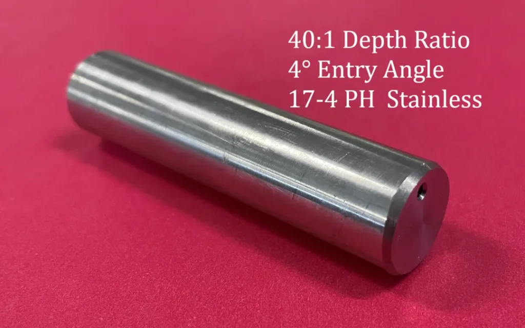
A test coupon for a part with a drilled hole at a 40:1 dept-to-diameter ratio at a 4 degree angled entry.

Key Takeaways

While dedicated deep hole drilling equipment is purpose-built for challenging features such as 40xD angled holes, a well-designed VMC process may be serviceable — particularly where small batch volumes do not justify capital investment in specialized equipment or an additional supply chain leg. This R&D effort confirms that with deliberate process design, a standard 3-axis VMC can produce a 40:1 depth-to-diameter hole in 17-4 PH stainless at a 4° angled entry and sustain tool life past 200 cycles. Therefore, a 40xD feature on a print is not automatically a reason to decline, subcontract, or invest in new equipment. It is a reason to ask whether a well-designed process on existing equipment can meet the specification.